
In optics, a thin lens is a lens with a thickness (distance along the optical
axis between the two surfaces of the lens) that is negligible compared to
the radii of curvature of the lens surfaces. Lenses whose thickness is not
negligible are sometimes called thick lenses.
The thin lens approximation ignores optical effects due to the thickness
of lenses and simplifies ray tracing calculations. It is often combined with
the paraxial approximation in techniques such as ray transfer matrix
analysis.
A single spherical interface between two transparent media can lead to
image formation. But viewing these images is not always possible.
Consider an air-glass interface. When the object is on the air side, the
image can only be viewed from inside the glass. Giving the glass a finite
thickness and adding a second spherical interface between glass and air
will produce an image that can be viewed by someone in air. A piece of
glass of finite thickness with two spherical boundaries is a lens. If the
thickness of the lens is much smaller than the diameter of the lens, we
call it a thin lens.
Thin lenses can be converging or diverging. Converging lenses are
thicker in the middle than near the edges, and diverging lenses are
thicker near the edges than in the middle. A thin lens has two focal
middle. A thin lens has two focal points, located on the optical axis, a
distance f from the center of the lens on either side of the lens. Rays
parallel to the optic axis passing through a thin converging lens come
together at the focus f on the opposite side of the lens, and rays parallel
to the optic axis passing through a diverging lens diverge as if they were
leaving the focus on the incident side on a straight line path.
A plane through a focus perpendicular to the optic axis is called a focal
plane. Parallel rays converge in the focal plane or diverge from the focal
plane, independent of the angle they make with the optic axis.
Thin lenses can form real and virtual images.
Let xo denote the perpendicular distance of the object from the
centerline of the lens and let xo be positive. Let xi denote the
perpendicular distance of the image from the centerline of the lens.
Then xi can be found from the lens equation
1/xo + 1/xi = 1/f,
Provided we use the following sign convention.
Xo is positive for an object in front of the lens.
Xi is positive if xo and xi are on the opposite sides of the lens.
Xi is negative if xo and xi are on the same side of the lens.
F is positive for a converging lens.
F is negative for a diverging lens.
The magnification is M = -xi/xo.
If M is negative, the image is inverted.
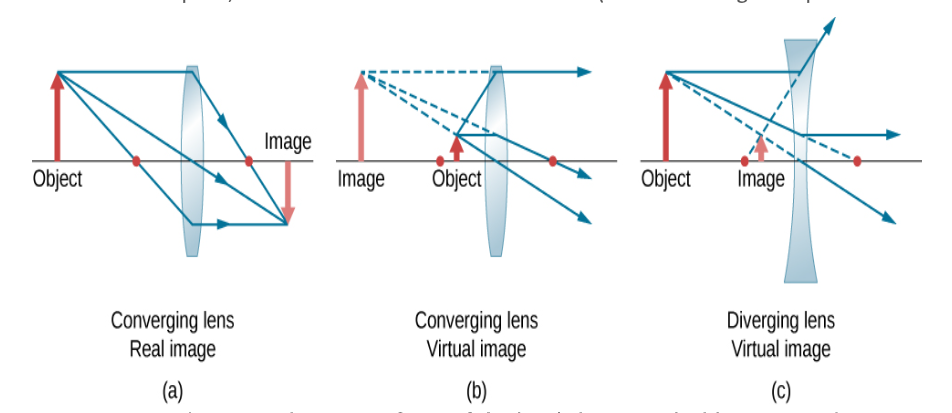
We can find the position and size of the image geometrically. Only two
rays must be drawn.
Draw the optical axis and the centerline of the lens.
Mark the position of the foci.
Draw the object in front of the lens. Draw an incident ray parallel to the
optical axis from a point on the object to the centerline of the lens, and a
refracted ray from the centerline through f.
For a converging lens draw the refracted ray through the focus on the
exit side, and for a diverging lens draw the refracted ray so that its
extension passes through the focus on the incident side.
Draw a second incident ray through f, and a refracted ray parallel to the
optical axis.
The incident ray, or an extension of the incident ray, must pass through
f. For a converging lens draw the incident ray or its extension through
the focus on the incident side, and for a diverging lens draw the incident
ray so that its extension passes through the focus on the exit side.
The intersection of the two rays marks the position of the image.
To check the accuracy of your drawing, draw a third ray through the
center of the lens. This ray is not bent. It should pass through the
intersection of the other rays that you have drawn.
IMAGE FORMATION BY THIN LENSES
We use ray tracing to investigate different types of images that can be
created by a lens. In some circumstances, a lens forms a real image, such as
when a movie projector casts an image onto a screen. In other cases, the
image is a virtual image, which cannot be projected onto a screen. Where,
for example, is the image formed by eyeglasses? We use ray tracing for thin
lenses to illustrate how they form images, and then we develop equations to
analyze quantitatively the properties of thin lenses.
USING THE THIN LENS EQUATION
The thin-lens equation and the lens maker’s equation are broadly applicable
to situations involving thin lenses. We explore many features of image
formation in the following examples.
Consider a thin converging lens. Where does the image form and what type
of image is formed as the object approaches the lens from infinity? This may
be seen by using the thin-lens equation for a given focal length to plot the
image distance as a function of object distance. In other words, we plot
di=(1/f−1/d⁰)−1
For a given value of f For f=1cm


